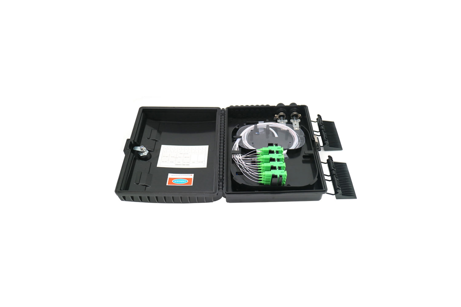
Telecom 8 Core Fiber Optic Splitter Terminal Box

Product Model

 SP-1602-8C

Product Description

SP-1602-8C fiber access termination box is able to hold up to 8 subscribers. It is used as a termination point for the feeder cable to connect with drop cable in FTTx network system. It integrates fiber splicing, splitting, distribution, storage and cable connection in one solid protection box.

Features

Features:

  1. Material: high quality impact resistant material ABS+PC
  2. 2 inputs use multi-fiber cable or uncut cable, 8 outputs for FTTH, convenient fast to operate.
  3. Fiber radius of curvature≥40mm
  4. Fiber splice tray additional loss≤0.01dB
  5. Temperature range -40℃~+70℃
  6. Anti-side pressure≥2000N/10cm
  7. Impact resistance≥20N.m
  8. For cable diameter, input side should be 7.0mm,output side should be 2.0mm,3.0mm indoor cable, or 2.0*3.0mm FTTH drop cable.
  9. It suitable for 8 SC Simplex adapter
  10. It fit for 1×4, 1×8 steel tube PLC Splitter
Application

Application:

This type terminal box is widely used in FTTH networks, telecommunications, CATV, data communications, LAN network and so on. It can be splicing or cold junction, application for a wide range, especially for multi-storey and high-level use of households.
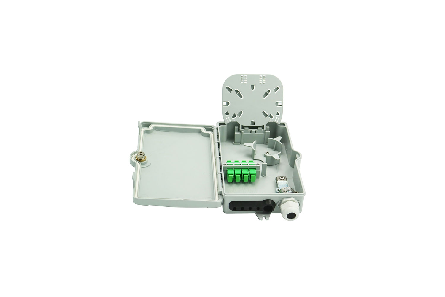
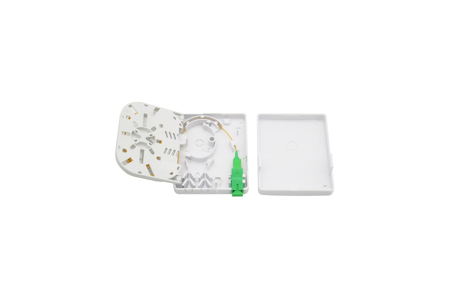
Advantages:

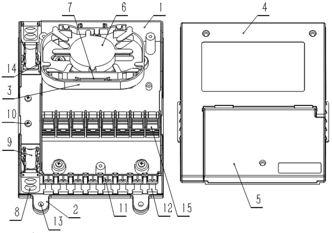
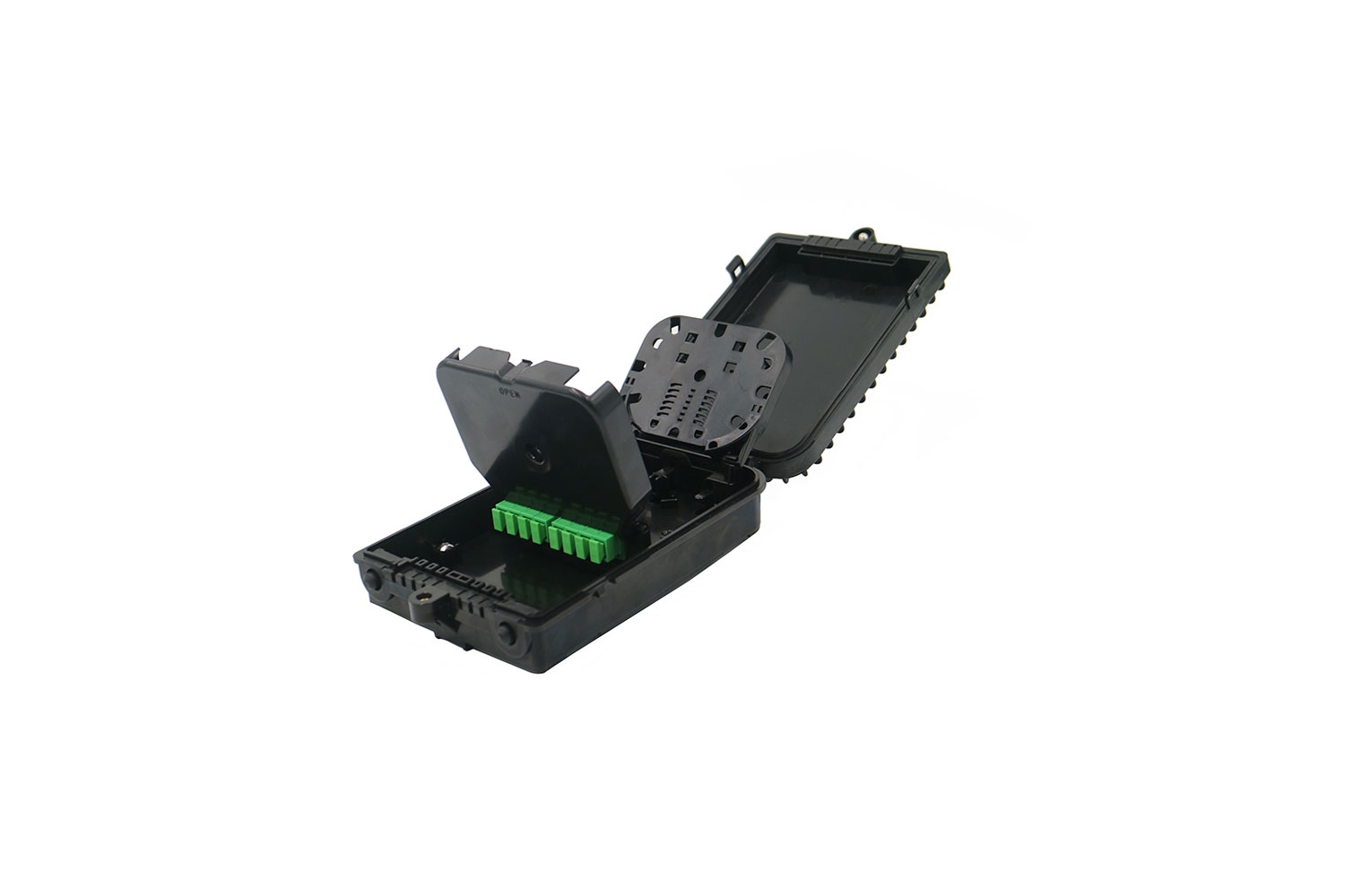
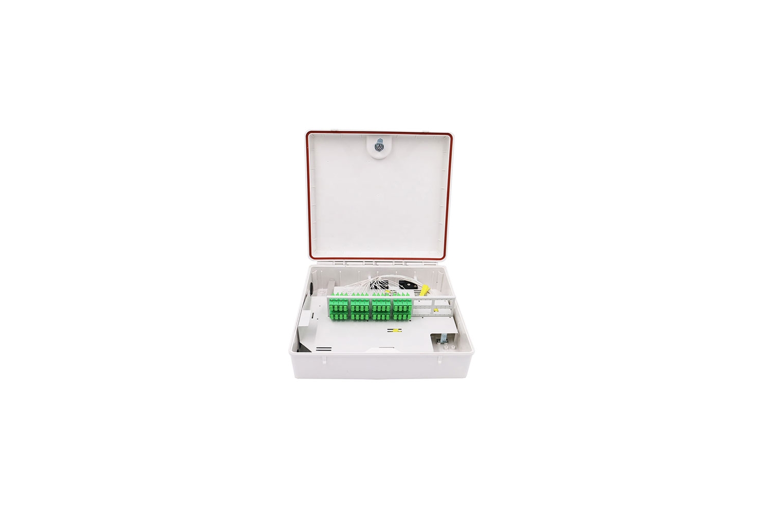
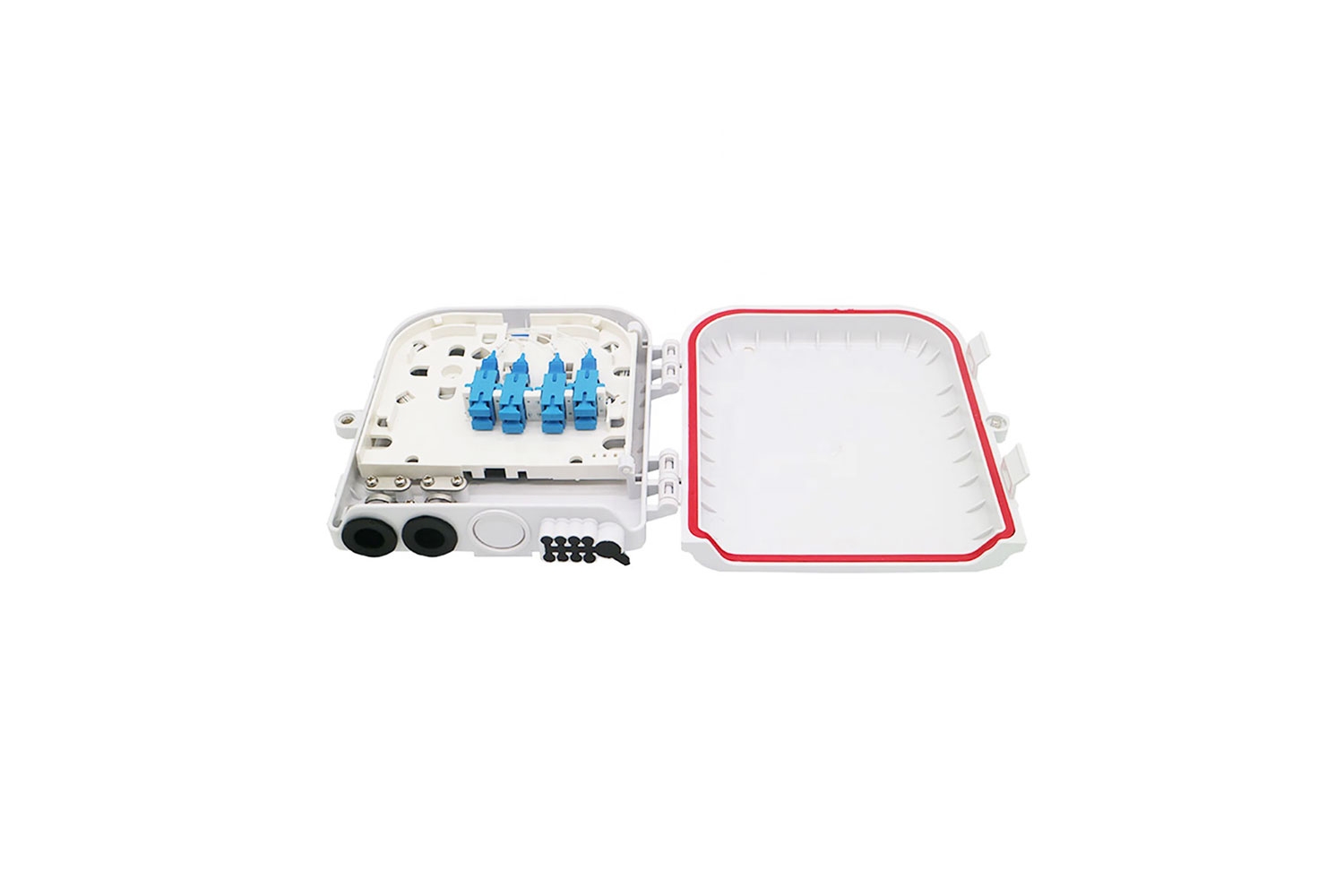
This type terminal box is more smaller size compare with other splitter boxes, it can accommodate 1×8 steel tube PLC Splitter. Adapter bracket is split structure, hinge connection with terminal box main body, can free flip 360 degree, so it is more easier to install and maintenance, will not affect the operation cause the small space. The design for splice tray not only increased the fiber storage space, also reduce the cable cross. The top cover can flip up to 90 degree, such unique design can improve efficiency for future maintenance and repair.

Install Method

Install Method:

Take the cable trough the symmetrical opening of the cable entry(8)into the box body, then through the cable compression bracket(9) and reinforce core fixing plate(10) to fix the cable well, then the cable through the terminal box(1) winding ring entry into the splice tray (6), and leads the cable to fiber fuse protection groove(7), and splicing with PLC Splitter input side cable; The fiber fuse protection groove can fix the heat shrink sleeves, can protect the fiber and avoid the damage; After splicing the PLC Splitter input side, then get connection with PLC Splitter output side connectors by adapters on adapter plate(15). Then connection the customer’s patch cords connector to adapter, and lead the patch cord or pigtail to output ports(11), then trough the box, and fix the cables by cable ties on outer cable fixed plate (12). Finally, wall mounted fix the terminal box on user’s desired position through the mounting fixing hole(13) of fixing plate(2).

Installation

Download

<h3>Telecom Box</h3>

Specification Download

Related Products

GETTING MORE DETAILS AND SPECIAL PRICE FROM US

Copyright © 2019 Shenzhen Spring Optical Communication Co., Ltd | All Rights Reserved